Mechanical Universal Testing Machine Manufacturers in Rajasthan
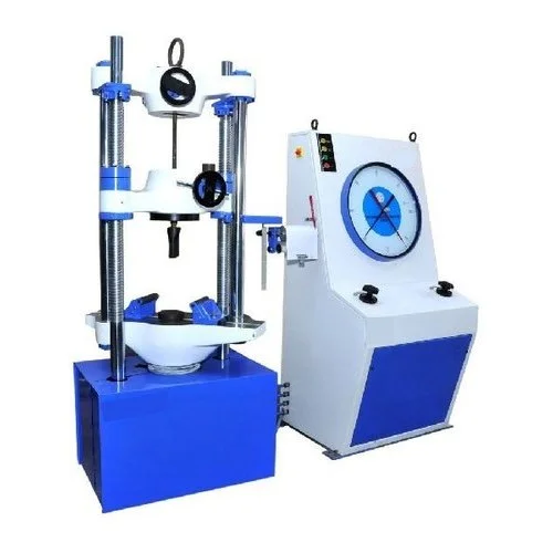
Mechanical Universal Testing Machine
We are Manufacturer, Supplier, Exporter of Mechanical Universal Testing Machine, Mechanical Universal Test Machine. Our setup is situated in Ichalkaranji, Maharashtra, India and majorly we serve customers from African and Gulf countries.
Features
- ⮚ Loading accuracy as high as ±1 %
- ⮚ Straining rate to cover a wide range of materials.
- ⮚ Motorised loading and unloading.
- ⮚ High reading accuracy due to large size and design diel.
- ⮚ Simple control to facilitate ease of operation.
- ⮚ Fully enclosed and protected load measuring system.
- ⮚ Wide range of standard and special accessories including load stabilizer.
- ⮚ Robust straining frame.
- ⮚ High reading accuracy due to large size and design diel.
- Motorised UP/DOWN movement of lower crosshead to enable easy and rapid fixing of test specimen.
Principle of operation
The test specimen is subjected to load with hydraulic system and is measured precisely with pendulum dynamometer. Load is applied by a hydrostatically lubricated ram.The oil pressure in the main cylinder is transmitted to the cylinder of the pendulum dynamometer housed in the control panel, the dynamometer piston exerts a force proportionate to the hydraulic pessure.This force is transferred through a leverage system to a pendulum. Displacement of pendulum actuates the rack and pinion mechanism which operates the load indicating pointer. Return movement of pendulum is effec- tively damped to absorb energy in the event of sudden breakage of specimen. Machine comprises ofthe following:
Straining Unit
This consists of a hydraulic cylinder & piston mounted on a robust base. The loading frame consists of an upper crosshead, middle crosshead and lower table. The upper crosshead and lower table is connected by means of two plain hard chrome plated columns. The middle cross head is fitted on two hard chrome plated threaded columns. A reduction gear motor drives the chain and sprockets fixed at the bottom of the threaded columns for height adjust- men!. The cylinder and ram is individually lapped to eliminate friction.Axial loading of the system is ensured by provision of a ball seating under the lowertable. An elongation scale with least count of 1 mm is provided for measurement of deformation on various samples. Tensile test is conducted by gripping the test specimen between the upper and middle crosshead.Compression, Transverse, Bending and Shear tests are conducted between the Shear tests are conducted between the middle crosshead and the lower table.
Application
Universal Testing Machine is designed to perform Tensile, Compression, Bending and shear tests on metal & Other materials both in the form of test pieces and as finished products.
Hydraulic System
The power pack has a directly driven pump which generates a maximum pressure of 200 kgf/cm2. he hydraulic pump producs a continuous non-pulsating oil flow. Hence the load application is very smooth. Oil filter, oil stranier, air breather, oil level indicator and drain plug is provided in the power pack. A pressure compensated flow to the main cylinder. This maintains constant rate of piston movement andhence straining rate is kept constant. This valve is hand operated and gives infinitely variable oil flow to obtain different rates of straining.
Control Panel
The control panel consists of the hydraulic system complete with drive motor, oil sump, pendulum dynamometer and the load indicating system.
Pendulum Dynamometer
The oil pressure in the main cylinder actuates the special dynamometer system. Pressurised oil in the loading cylinder pushes up the measuring piston proportionately and deflects the pendulum. The piston is constantly rotated to eliminate friction. The system has effective damping arrangement to ensure smooth return of pendulum aftersudden breakage of test piece. This unit permits selection of favourable hydraulic ratios producing relatively small frictional forces.
Load Indicating System
This system consists of a large dial and a pointer. Displacement of pendulum actuates the rack and pinion mechanism, which operates the load indicating pointer. The pointer moves over a large dial indicating the load. A dummy pointer is provided toregister the maximum load reached during the test. Window type dial is provided for easy and clear changing of load range.
Load / Elongation Recording System
A continuous roll ( A strip chart) type load-elongation recorder is provided for plotting load-elongation graph. Horizontal movement of the rack produces load ordinate of the diagram and drum rotation to elonga-tion ordinate, in the ratio of either 1:5 or 1:10.
Electronic Universal Testing Machine-
Construction: TestCraft
make electronic Universal Testing machines comprised of
a. Loading Unit:
This is similar to the standard loading unit of analog type universal testing machine. In addition to standard features of the regular loading unit, a ROTARY ENCODER is attached to the hydraulic ram to get the accurate displacement of the ram.
b. Measuring Control Panel:
This includes,