Hydraulic Grip Front Loading UTM with Servo Control System manufacturers in pune
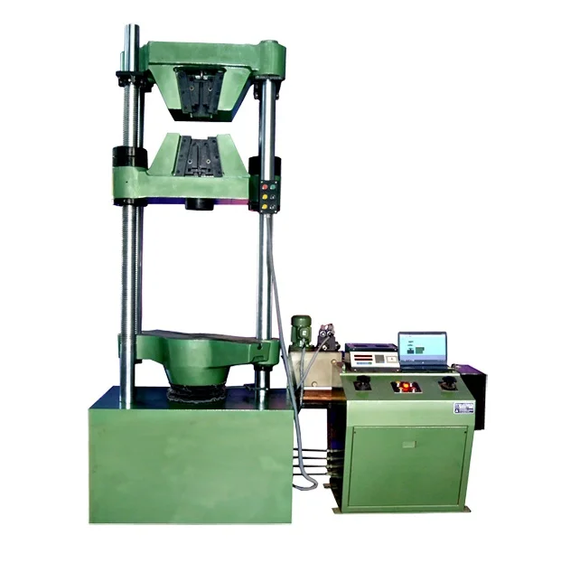
Hydraulic Grip Front Loading Universal Testing Machine with Servo Control System
We are Manufacturer, Supplier, Exporter of Hydraulic Grip Hydraulic Grip Front Loading Machines, Hydraulic Front Loading Machine, Hydraulic Hydraulic Grip Front Loading Machines. Our setup is situated in Ichalkaranji, Maharashtra, India and majorly we serve customers from African and Gulf countries.
Features
- ⮚ Open type cross head
- ⮚ Hydraulic wedge action grips
- ⮚ Long test stroke and test space
- ⮚ Servo controlled Motorized Valve incorporating of control modes - Standard manual control, Load rate control, Elongation rate control, Load hold mode, Auto start & initial valve open start.
- ⮚ Loading accuracy as high as + 1% Straining at variable speeds to suit a wide range of materials.
- ⮚ Printer & PC graphs enable study the behavior of the material.
- ⮚ Manual control & release valve operation
- ⮚ Load Capacity : 100 kN, 200 kN, 400 kN, 600 kN & 1000 kN
Principle of Operation for - Model: UTES-HGFL
UTM right control valve is Servo Controlled in close loop mode as per mode selection. Following control modes available:
1. Standard Manual control
2. Load rate control
3. Elongation rate control
4. Load hold mode
Also, Autostart, Potentiometric start &initial value open start options are available for test to start to take care of slippage & different specimen types. Load is applied by a hydrostatically lubricated ram.
Main cylinder pressure is transmitted to the pressure transducer housed in the control panel.
The transducer gives the signal to the electronic display unit, Corresponding to the load exerted by the main ram. Simultaneously the encoder fitted on the straining unit gives the mechanical displacement.
Straining unit
This consists of a cylinder motor with chain and sprocket drive and a table coupled with the ram of the hydraulic cylinder, mounted on to a robust base. The cylinder and the ram are individually lapped to eliminate friction. The upper cross-head is rigidly fixed to the table by two strengthened columns. The lower cross-head is connected to two screwed columns which are driven by a motor. Axial loading of the ram is ensured by relieving the cylinder and ram of any possible side loading by the provision of ball seating. An displacement scale, with a minimum graduation of 1mm, is provided to measure the deformation of the specimen. Tension test is conducted by gripping the test specimen between the upper and lower cross-heads. Compression, transverse, bending, shear and hardness tests are conducted between the lower cross-head and the table. The lower cross-head can be raised or lowered rapidly by operating the screwed columns, thus facilitating ease of fixing of the test specimen. Typical HGFL design includes a basic universal testing machine frame with open type crossheads and hydraulic wedge action grips.
Typical HGFL design includes a basic universal testing machine frame with open type crossheads and hydraulic wedge action grips.
Application
Electronic Universal Testing Machine is designed for testing materials and other materials under tension, compression bending, transverse and shear loads. Hardness test on metals can also conducted. Machine Consists of
Control Panel
The Control Panel consists of a power pack complete with drive motor and an oil tank, control valves and electronic display unit.
Power Pack
The power pack generates the maximum pressure of 200 kgf/cm2. The hydraulic pump provides continuously non-pulsating oil flow. Hence the load application is very smooth.
Hydraulic Controls
Hand operated wheels are used to control the flow to and from the hydraulic cylinder. The regulation of the oil flow is infinitely variable. Incorporated in the hydraulic system is a regulating valve, which maintains a practically constant rate of piston movement. Control by this valve allows extensometer reading to be taken. Another Power pack is used to operate wedge action grips by means of hydraulic cylinder by using solenoid valve operation For Hydraulic Wedge action grips separate control remote is provided with selector switches indicating clamp - declamp and null positions.p>
Accuracy and Calibration
Electronic Universal testing machine is closely controlled for sensitivity, accuracy and calibration during every stage of manufacture. Machine is calibrated over each of its measuring range in accordance with the procedure laid down in British standards 1610: Part1: 1992 and IS 1828: Part1: 1991. Electronic Universal Testing Machine complies with Grade “A” of BS: 1610:Part1:1992 and class 1 of IS-1828- Part1:1991.